Structure
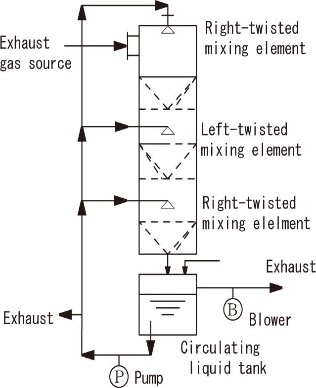
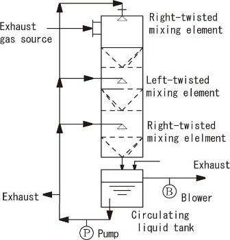
MU Scrubber is a static mixer with a mixing wing “MU Mixing Element” for stirring, which has a high performance gas-liquid contact efficiency built into a cylindrical column body. The MU Mixing Element is a spiral wing with right or left twist. Exhaust gases containing fine particles and chemicals are supplied from the top of MU Scrubber.
On the other hand, the cleaning fluid supplied from a lower tank of the equipment by a pump is injected inside a tower through spray nozzles installed in spray pipes on the side of tower’s body. While absorbing the chemical substances and dust contained in exhaust gas, this cleaning solution drops from the upper part of the tower to the lower part, collects in the downstream tank, and circulates into the tower again. In other words, while exhaust gas passing through the column and circulating liquid are flowing in parallel through MU Mixing Element installed in the column, gas and liquid are completely mixed and contacted by repeating the division, merging, shearing and spiral rotation in the right and left directions.
First, the effect of this method is to capture substances contained in exhaust gas. As described above, it increases the gas-liquid contact efficiency to achieve high-efficiency capture. The chemical substances in the exhaust gas are chemically absorbed, and the inert substances are physically dissolved and absorbed in the cleaning solution. In addition, fine particles of dust in exhaust gas grow and coarsened by agglomeration and swelling during the flowing through the equipment. In addition, it is trapped by fine bubbles generated in the column due to strong mixing of gas and liquid. Therefore, fine particles can be easily captured by the cleaning solution and suspended in the cleaning solution. As a result, exhaust gas is purified.
The second is to trap substances from exhaust gases without clogging the equipment. This is due to the interaction between the gas-liquid mixed flow of exhaust gas and cleaning fluid, and MU Mixing Element. Clogging of pores on the front and back surfaces of wings due to adhesion growth of reaction products and dust, etc. and the growth on the wall of the equipment are prevented.
The third is the reduction of pressure loss during the flowing at the treatment of exhaust gas. This is the effect of reducing pressure loss based on the structure of MU Mixing Element. In addition, the discharge of circulating cleaning fluid from the spray nozzle of the spray pipe inside the body of the tower creates an ejector effect, contributing to further reduction of pressure loss.
In this exhaust gas treatment process, new liquid is supplied to MU Scrubber as appropriate. This is to control the gas-liquid temperature, and cooling is usually performed using the sensible heat and evaporation heat of the new liquid. In addition, a heat exchanger can be installed in the circulating fluid line to cool or heat the circulating fluid from the outside. Another purpose of introducing new liquid is to control the concentration of captured substances in the circulating effluent in a tank, and to discharge the effluent containing the captured substances while maintaining the level of the tank.
Principles of Mixing
As shown in Fig. 1, spiral wings with right-twist (right turn) and left-twist (left turn) are installed on the inner circumferential surface of the column, and several right-twist/left-twist wings are alternately arranged through the space. The wing has a large number of pores. The exhaust gas and the cleaning fluid flow in parallel, and while these flows through wings twisted to the right spirally, the gas-liquid mixed contact is made by dividing, merging, and shearing action in the horizontal and vertical directions. Then, they meet in a void part. Next, they are mixed and contacted by subdividing and shearing action by wings twisted to the left spirally. In this way, gas and liquid are in complete mixed contact while continuously repeating the multiple division, swirl, confluence, inversion, and radial and axial shear actions.
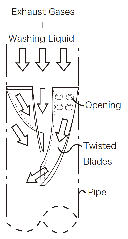
Figure 1 Schematic diagram of gas-liquid contact by built-in MU Mixing Element
Mixing Test
There are two points to obtain good gas-liquid mixing and contact conditions using MU Scrubber.
- Increase the liquid to gas ratio (Gas flow rate is constant)
- Increase gas flow rate (The liquid/gas ratio is constant)
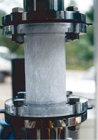
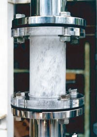
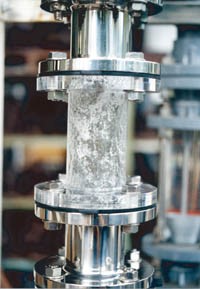
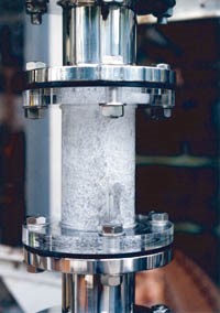
To confirm these two points, we placed a small MU Mixing Element in a tube with an inner diameter of 72 mm as shown in Fig. 2, and conducted a test in which water flows from the top to the bottom and air at room temperature flows in parallel with water. The transparent tube portion in Figure 3 is a cavity in a space part between two MU Mixing Elements. It allows the visual observation of the mixture of air and water and shows the test results under several conditions. First, the water/air ratio was changed to 8-70 l/m3 at air velocity of 10 m/sec. At this time, if the water/air ratio drops to 8 l/m3, it is poorly mixed (Photo (d)), but if the range is 15-70 l/m3 (Photos (a) – (c)), it is well mixed.
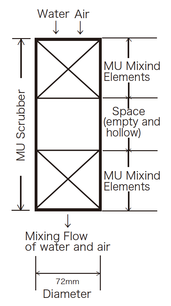
Figure 2. Schematic diagram of MU Scrubber settings for observation (The diagram shows a photographed part.)
The air flow rate was then halved to 5 m/sec. Under this condition, the mixing condition with water/air ratio of 15 l/m3 was poor (Photo(e)). On the other hand, under the condition of flow velocity of 10 m/sec, the mixing was in a good status as shown in the photo © even with the same water/air ratio of 15 l/m3. This shows that faster flow rates result in better mixing. Under this condition, the mixing condition with water/air ratio of 15 l/m3 was poor (Photo(e)). Even at a flow rate of 5 m/sec, which is half of 10 m/sec, the mixture was again better when the water/air ratio was increased to 35 l/m3 (Photo(f)). Based on these tests, it was observed that the mixing state of gas and liquid was good when the liquid-gas ratio and the gas flow rate increased, respectively, and deteriorated in the opposite case.
Fig 3. Photo of Gas-Liquid Mixed Status
| Photo (a) | Photo (b) | Photo (c) |
 |
 |
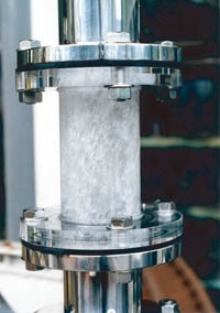 |
| Flowing amount per unit area:3,500m3/m2h | Flowing amount per unit area:3,500m3/m2h | Flowing amount per unit area:3,500m3/m2h |
| Gas Velocity: 10m/sec | Gas Velocity: 10m/sec | Gas Velocity: 10m/sec |
| Liquid/Gas ratio:70ℓ/m3 | Liquid/Gas ratio:45ℓ/m3 | Liquid/Gas ratio:15ℓ/m3 |
| Photo (d) | Photo (e) | Photo (f) |
 |
 |
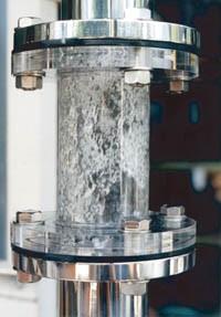 |
| Flowing amount per unit area:3,500m3/m2h | Flowing amount per unit area:1,800m3/m2h | Flowing amount per unit area:1,800m3/m2h |
| Gas Velocity:10m/sec | Gas Velocity:5 m/sec | Gas Velocity:5m/sec |
| Liquid/Gas ratio:8ℓ/m3 | Liquid/Gas ratio:35ℓ/m3 | Liquid/Gas ratio:15ℓ/m3 |
(* Liquid-gas ratio = Amount of liquid (l/h)/Amount of gas (m3/h))
Eight Features
01 Enabling the compact installation on the exhaust line
The gas superficial velocity is 2-20 m/sec and can be installed in the middle of exhaust pipe. Since the gas and liquid flow is in parallel, flooding does not occur, the scrubber can be operated at a maximum of 20 m/sec of flow rate in the column. Compact design reduces equipment costs.
02 Low pressure loss
During operation, as gas flows through the column, liquid is circulated. The liquid-to-gas ratio is in a range of 0.2-500 l/m3, but in order to obtain good gas-liquid contact, set the high liquid-to-gas ratio to 50-500 l/m3 near the minimum gas flow rate of 2 m/sec. At the maximum flow rate of 20 m/sec, the liquid-gas ratio is as low as 0.2-20 l/Nm3. When low pressure loss is required, operation with zero pressure loss is also possible by reducing the flow velocity in the column or the liquid gas ratio. On the other hand, under conditions of high flow velocity and high liquid-gas ratio, which maximizes the gas-liquid contact efficiency, the pressure loss may increase over less than 3 kPaG in normal operation.
03 No clogging Maintenance free
Even under extremely demanding gas-liquid mixing conditions, such as the treatment of highly adhesive dust or the deposition of solid materials such as metal oxides in gas-liquid contact areas, clogging due to products is completely prevented, enabling long-term continuous operation (A track record of continuous operation for 15 years with over 8,000 hours/year). When cleaning the equipment after long-term operation, disassembly and cleaning of the equipment can be performed easily.
04 High performance of capture of dust, mist and chemical substances
The removal efficiency is more than 90-99.99% for chemical absorption per tower. More than 99.999% is possible depending on how the process is constructed, but it also depends on the nature of the chemical substance. The removal efficiency of dust and mist of 1 micron or less is usually 90% or more, but it varies depending on the compatibility with cleaning fluid. If further improvement of removal efficiency is required, it is usually easy to increase the number of elements.
05 Suitable for both low and high concentration gas treatment
Even exhaust gas containing highly concentrated chemical substances of several tens of volume% or more can be easily treated. It does not need to be diluted with air or nitrogen. In addition, because of its high gas-liquid contact efficiency, it is also suitable for the treatment of chemical substances with low concentrations of several tens of ppm by volume.
06 Because of its high gas-liquid contact efficiency, it can be designed simply assuming that vapor-liquid equilibrium is achieved.
Based on vapor-liquid equilibrium data for chemical absorption, phase change of vapor condensation, or physical absorption based on Henry’s law, determine the composition, temperature, and required heat quantity of the vapor-liquid for designing the column. For absorption and desorption of chemical substances in gas and liquid, we have confirmed in some examples that gas and liquid equilibrium is reached in MU Scrubber. When the cleaning fluid is water, evaporation and condensation of water reach vapor-liquid equilibrium.
07 Capturing and cooling can be performed simultaneously.
It catches dust and chemical substances from exhaust gas and also cools gas and liquid at the same time. This concurrency is an advantage of MU Scrubber.
08 Not only parallel flow type but also counter flow type is used according to the purpose.
In certain specific cases, MU Scrubber can be designed as counter flow. In this case, the number of theoretical plates is calculated by applying the concept of a distillation column to multi stages of MU Mixing Element. At this time, if the absorption rate of the substance is slow, the number of stages will be large. In absorption, the concentration of chemical substances in the effluent is increased and the concentration of chemical substances in the exhaust gas is reduced to an extremely low level. On the other hand, when used for emission, a high concentration of chemical substances is recovered as gas from the absorbent and the concentration of chemical substances in the absorbent remaining after emission is reduced as much as possible. A combination of parallel and countercurrent flows may also be used as an optimal design.
Examples of application and arrangement
The MU Scrubber is used for cleaning exhaust gas and recovering chemical substances from exhaust gas. Its applications are as follows.
- Treatment of exhaust gas containing HCl, Cl2, HF, SOX, NH3, NOX, Hg, DXN’s, etc.
- Exhaust gas treatment for forming metal oxide solid by contact of water with silicon tetrachloride, silicon trichloride, silicon dichloride, silicon fluoride, titanium tetrachloride or the like
- Dust removal of metal oxides such as SiO2 and ZnO in exhaust gas
- Deodorization by absorption of trace malodorous components such as ammonia, triethylamine and hydrogen sulfide
- Sterilization and sterilization of organisms such as bacteria and viruses in exhaust gas by ozone gas, etc.
- Recovery of chemicals such as NH3 and HCl from exhaust gas
- Dust removal and recovery of chemical substances
The following chapter shows five installation examples.
![[Exhaust gas dust removal tower] Dimensions φ1800 x 8 mH](https://mu-company.com/en/cms/wp-content/uploads/2020/04/9fb2f19e9a1207a1ff2136319243b2dd-scaled.jpg)
[Exhaust gas dust removal tower] Dimensions φ1800 x 8 mH
![[CVD exhaust gas treatment product] CIMG 2669](https://mu-company.com/en/cms/wp-content/uploads/2020/04/83fc995f970aac635b25991e8a8432ff-scaled.jpg)
[CVD exhaust gas treatment product] CIMG 2669
![[HCl gas absorption tower] Dimensions 900 A x 20 mH](https://mu-company.com/en/cms/wp-content/uploads/2020/04/d30987b6b02c39d5292e3a0f5892db5f.jpg)
[HCl gas absorption tower] Dimensions 900 A x 20 mH
![[TiCl4 absorption tower] Dimensions 500 A x 9 mH](https://mu-company.com/en/cms/wp-content/uploads/2020/04/635a32c4486eacb1cd01309d03892da2.jpg)
[TiCl4 absorption tower] Dimensions 500 A x 9 mH
Examples of installation of MU Scrubber
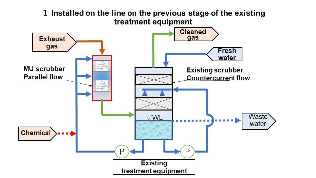
1. Installation on the front and rear line of existing treatment equipment
We assumed a process to enhance the treatment of exhaust gas by installing additional pipes in the middle of existing pipes.
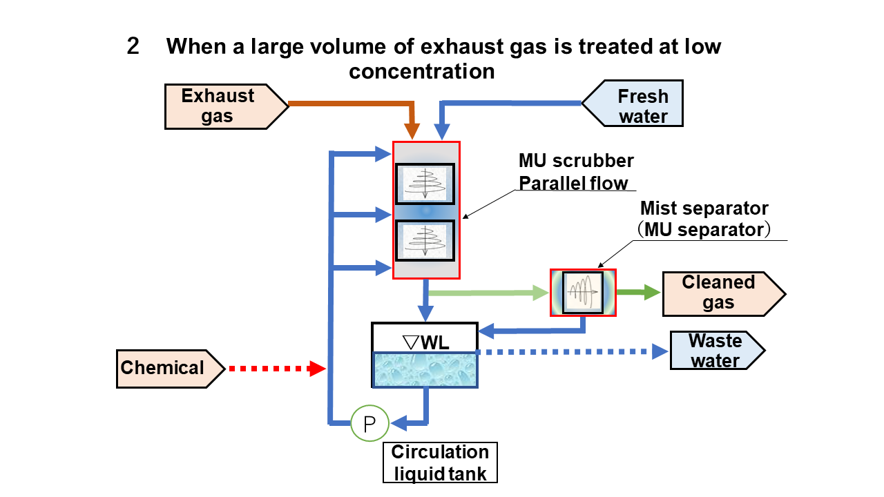
2. When a large volume of exhaust gas is treated at low concentration
It was assumed that the exhaust gas was finally treated by MU Scrubber to release clean gas into the atmosphere. Mist entrained in exhaust gas is usually collected by mist separator (MU Separator). The figure shows an example of installation of a mist separator (MU Separator). Traditionally, dust and mist may adhere to the inside of the exhaust gas suction blower and grow. But, the flow in this diagram shows our product solves the problem. Single column system with parallel flow is particularly advantageous for the treatment of low-concentration, high-capacity gases.
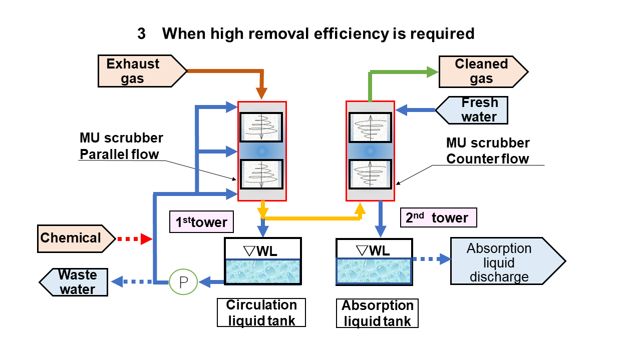
3. When high removal efficiency is required
There are several combinations of MU Scrubber for high chemical removal efficiency, recovery and dust removal. The figure shows an example of a process in which dust is removed by parallel flow in the first tower, and exhaust gas is cleaned by absorbing chemical substances in the counter flow in the second tower. The first tower removes dust and the second tower removes chemical substances from exhaust gas with high removal rates. At the same time, the second tower can recover chemical substances into an absorbent liquid in a highly concentrated solution. The cleaning solution for the first column uses a saturated solution of chemical substances, so absorption of chemical substances does not occur.
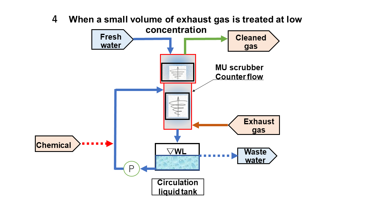
4.When a small volume of exhaust gas is treated at low concentration
A countercurrent tower system is effective for treating small amounts of gas at low concentrations. Reaction/absorption is performed in the lower stage, and complete absorption is performed in the upper stage.
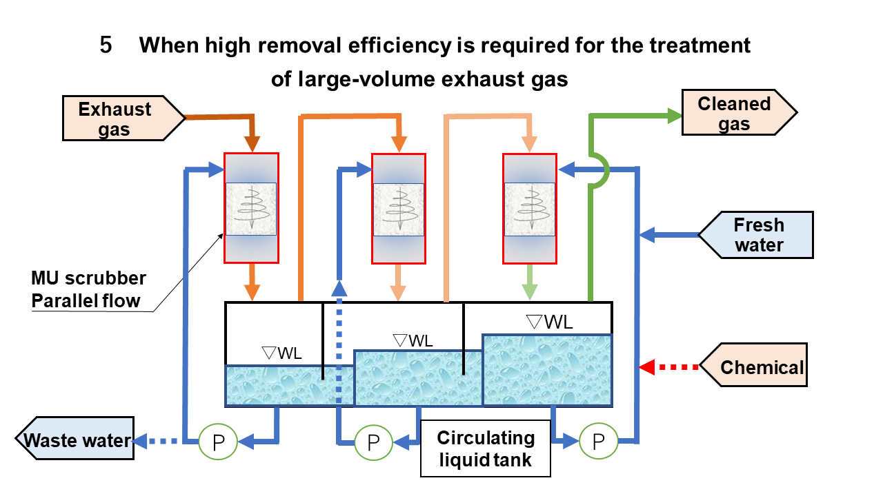
5.When high removal efficiency is required for the treatment of lage-volume exhaust gas
This is a parallel flow tower in series and is applied to the treatment of exhaust gas with a larger capacity than 3. Each column becomes compact due to the parallel flow, and by serializing it, large-capacity exhaust gas can be treated with high removal efficiency. Some systems with significant heat generation may have coolers in the circulation line.
About inquiries
The following design conditions must be disclosed when making inquiries to MU Scrubber. The purpose is to examine the process and equipment specifications after determining the suitability of the application of MU Scrubber. The following shows almost full design conditions. We would like to receive your conditions based on the required accuracy of examination.
-
-
- Treated flow: () Nm3/h
- Gas temperature: Operation () ° C, Design () ° C
- Gas source pressure: Operation () kPaG, Design () kPaG
- Pressure at the inlet of equipment: Operation () kPaG, Design () kPaG
- Distinction between components contained in exhaust gas and gases, liquids and solids: Regarding contained components a., b., c ………
- Distinction between components contained in exhaust gas and gases, liquids and solids: Regarding contained components a., b., c ………
- Concentration of components after treatment: Components a., b., c ……… are expressed in clear units such as ppm by volume and mg/Nm3.
- Maximum allowable pressure loss: Operation () kPa, Design () kPa
- Location: Exterior or Interior
- Footprint: Width, Depth, Height
- Explosion-proof measures: Required or Not required
- Power supply: Voltage, etc.
- Materials: Designated or Not designated In the case of designation, specify the material, such as PVC, FRP, SUS, titanium, etc., for the following parts as shown below. Body of the column, mixing element, circulating fluid tank, liquid piping, gas piping, circulating fluid pump, air exhauster, flange, gasket, bolt and nut, frame and basement
- Spare parts: mixing elements, spray nozzles, gaskets, bolts and nuts
- Operation Status: operation hour (hr/day), Batch/Continuous
- Supply of fresh liquid: name of substance, temperature, pressure, dissolved substance concentration, pH, specific gravity, viscosity
- Discharge fluid: name of substance, temperature, concentration of dissolved substance
- Use of existing information: disclosure of flow sheets for existing facilities, problems with existing facilities, and test data
- Utility conditions: disclosure of utility information required for exhaust gas treatment
-
Various comparison
Comparison of gas-liquid contact mechanism between MU Scrubber and conventional scrubbers
| Type | Gas-Liquid Contact Status | |
|
Jet scrubber Venturi scrubber |
Dispersed Liquid Type | 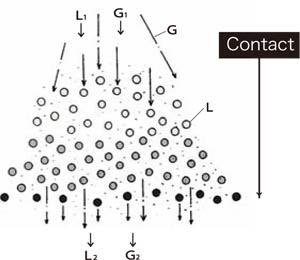 |
| Packed bed column | Dispersed Liquid Type |  |
| Spray column | Dispersed Liquid Type | 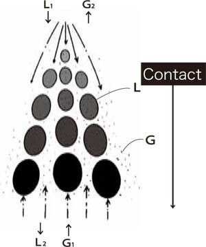 |
|
Perforated-plate column Tray column |
Dispersed Gas Type | 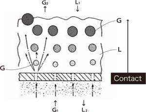 |
| MU Scrubber | Dispersed Liquid Type | 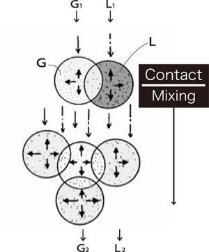 |
Table4-1. Schematic diagram of gas-liquid contact
| Type of Flow | Type of Gas-Liquid Contact | Gas-Liquid Contact Status | |
|
Jet scrubber Venturi scrubber |
Parallel-current | Agitation | 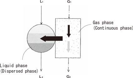 |
|
Packed bed column Spray column |
Countercurrent | Agitation | 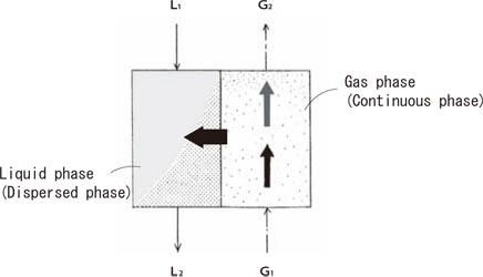 |
|
Perforated-plate column Tray column |
Countercurrent | Agitation | 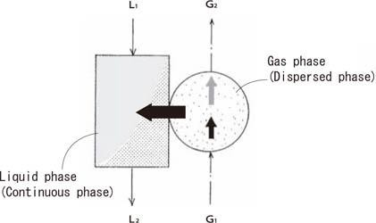 |
| MU Scrubber | Parallel-current | Mixing | 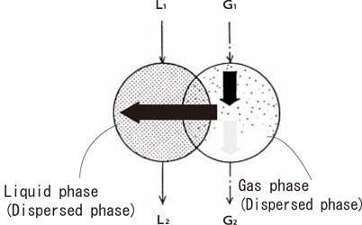 |
Table4-2. Schematic diagram of mass transfer from the gas phase to the liquid phase
Comparison of performance between MU Scrubber and conventional scrubbers
| Jet Scrubber | Packed Scrubber | MU Scrubber(Static Mixing Scrubber) | |
| Schematic view | 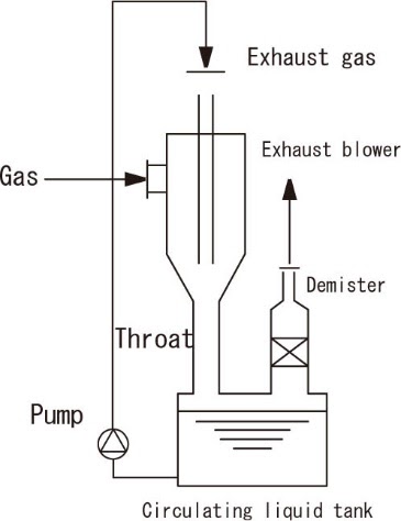 |
 |
 |
| Removal efficiency(%) | 99-99.5% | 90-99 | 90-99.999 |
| Processable concentration | several100ppm-several1% | several100ppm-several1% | several10ppm-100% |
| Amount of gas flow |
Suitable for small gas flow (10-200ℓ/min) |
Suitable for large gas flow (1-100m3/min) |
Suitable for both small and large gas flow (1-13,000m3/min) |
| Clogging inside apparatus | None | Sometimes many due to concentrated dusts and chemicals | None |
| Pressure drop(kPa) | 3-5 | 0.2-1 | 2-20 |
| Effect on removal efficiency by change of gas flow | Small (adjustable by bypass line) | Small | Small |
| Space velocity (m/sec) | Flow speed of throat 30 | 0.3-2 | 2-20 |
| Liquid-gas ratio (L/m3) | 1,000-3,000 | 0.5-5 | 0.2-500 |
| Features |
・High removal efficiency ・No nozzle clogging by dust mixing ・Forced liquid-gas mixing condition can be made in throat by liquid atomization with high pressure |
・Less pressure drop ・Small amount of circulating liquid |
・High removal efficiency ・No nozzle clogging by dust mixing ・No flooding phenomenon ・Suitable for simultaneous processing of gas cooling, gas absorption and dust removal ・High-performance mixing blades called ・MU Mixing Element”are placed inside towers |
Table5-1 Comparison of performance between MU Scrubber and conventional scrubbers
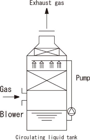
| Bubble Column / Scrubber | Packed Scrubber | MU Scrubber(Static Mixing Scrubber) | |
| Schematic view |  |
 |
 |
| Removal efficiency(%) | 99-99.5% | 60 | 90-99.999 |
| Processable concentration | several 100ppm ー several % | several 100ppm ー several % | several 100ppm ー several % |
| Amount of gas flow |
Suitable for large gas flow (several m3/min – several 100 m3/min) |
Suitable for large gas flow (several m3- 100m3/min) |
Suitable for both small and large gas flow (1-13,000m3/min) |
| Clogging inside apparatus | Relatively little compared with Packed Scrubber | Little | None |
| Pressure drop(kPa) | 3-5 | 0.2-1 | 0.5-3 |
| Effect on removal efficiency by change of gas flow | Large | Large | Small |
| Space velocity (m/sec) | 1-3 | 0.2-1 | 2-20 |
| Liquid-gas ratio (L/m3) | 1-3 | 0.2-1.5 | 0.2-500 |
| Features |
・Simple structure ・More effective than Packed Scrubber in general |
・Simple structure ・Generally utilized as previous step of absorption |
・High removal efficiency ・No nozzle clogging by dust mixing ・No flooding phenomenon ・Suitable for simultaneous processing of gas cooling, gas absorption and dust removal ・High-performance mixing blades called “MU Mixing Element”are placed inside towers |
Table5-2 Comparison of performance between MU Scrubber and conventional scrubbers